Branford Bike - Started in June, 1976 Branford Bike
129 Sagittarius Skyway, PO Box 1711, Emigrant, MT 59027 USA
Click on the underlined text to:
order online via our Secure Order Form and receive FREE...
or send us an email  with your questions or comments.
Phone Answering Hours M-W-F, 12 noon - 3 PM Mountain Time
Information: (203) 488-0482  FAX: (203) 643-8078
 
Hubs and Derailleurs Section: Page 15

Click on an underlined item or scroll down this page to view everything.

- Rear Derailleur Overhaul -

- Derailleur Parts, Tools and Maintenance Tips -

Order online via our - Secure Order Form - and receive FREE...

 
Rear Derailleur Overhaul
 
 
Level of Difficulty   to
Tools and Supplies

This article will discuss the overhaul of Shimano® and Campagnolo® rear derailleurs, which share many service features. The internal overhaul of the SRAM® X.0 rear derailleur will also be discussed. The Mavic® Mektronic will also be reviewed, although user service is limited. It should be noted that every model of every brand cannot be overhauled. See also related articles:

Rear Derailleur Overhaul

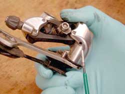
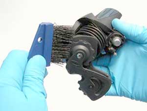
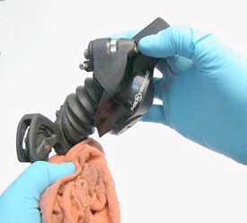
Some rear derailleur models allow the internal servicing in order to clean and lubricate. This often improves performance by removing dirt from pivots. Additionally, some models allow for the changes to the pulley cage tension spring. There are also after-market top pivot "break-away" bolts, which may be installed in place of the original mounting bolt.

It will be useful to have a note pad and pen to help you remember correct orientation of parts. Sketch any parts that seem unfamiliar, or 
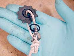
use a digital camera for the same purpose. Have some wire ties or twine on hand to help tie parts in their correct orientation as they come apart.

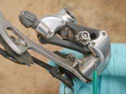
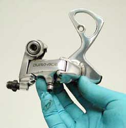
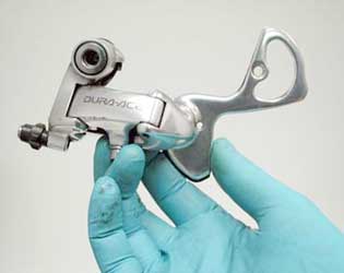
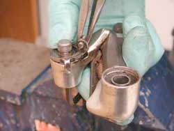
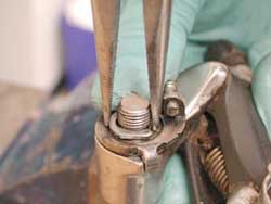
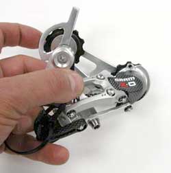
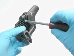
Begin by removing the rear derailleur from the bike. Loosen inner wire pinch bolt and pull inner wire from adjusting barrel. Remove the chain if it has a master-link. Loosen derailleur mounting bolt and remove derailleur from bike.

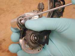
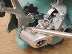
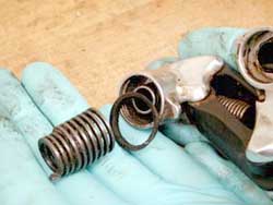
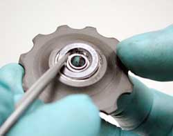
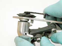
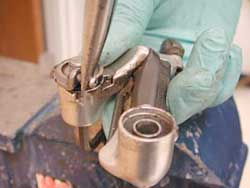
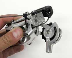
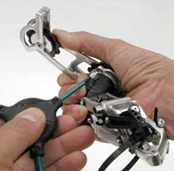
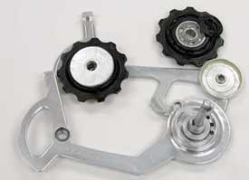
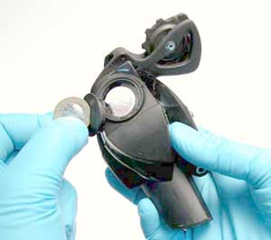
For bicycle chains with no master-link, the cage may be dismantled, 
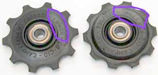
which allows the chain to stay together. Note and record any marking distinguishing upper and lower pulley. Also note the orientation of the cage. Loosen and remove both derailleur pulley bolts. Remove the cage and chain from the derailleur.

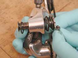
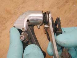
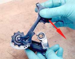
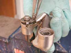
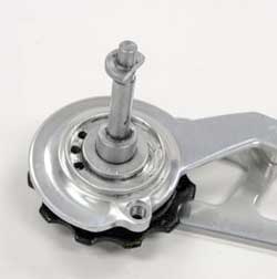
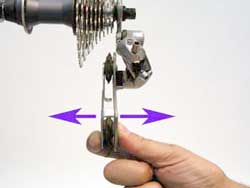
The derailleur may contain a tension spring in the upper pivot, at the mounting bolt. This spring controls the angle of the derailleur body. The mounting bolt spring and cage pivot spring oppose one another. Changing tension in the upper pivot relative to the lower pivot will move the derailleur body and upper pulley wheel relative to the cogs. Generally, it is desirable to have the upper pulley ride close to the cogs. Check the cog to pulley position when the chain is on the largest rear cog and the smallest front ring. If the largest cog is actually rubbing against the upper pulley, move the derailleur body back to move the pulley away. For 
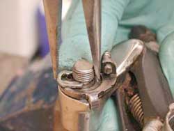
derailleurs with the spring in the upper pulley, increase the spring tension by tightening the "B" screw, found in adjacent to the top bolt. If there is a large gap between pulley and cog, the screw should be loosened.

Generally, the upper pivot spring tension should not be increased to solve the problem of chain slap or chain suck. Chain slap may be reduced slightly by this procedure, but chain suck is typically the result or worn or bent chain ring teeth, or a worn chain. Increasing the derailleur cage tension tends to have a marginal effect of chain suck. For chain slap, it is preferable to increase the tension of the pulley cage. There are limits to this procedure, as the upper mounting bolt spring tension opposes the cage spring tension. Increasing the cage spring tension will require an increase in the mounting bolt spring tension. If the derailleur B-screw is at it's limit, it is not advisable to increase cage tension.

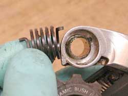
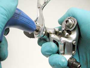
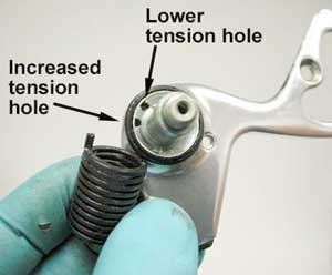
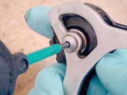
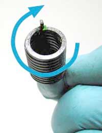
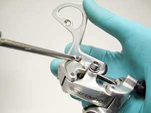
Campagnolo® derailleurs locate the B-screw in lower cage pivot. The upper spring tension is fixed. Tightening the B-screw will increase tension of the cage, allowing the pulley to move toward the cogs. Loosening the B-screw will decreases spring tension at the cage, allowing the upper pulley to move away from cogs. The screw turns a toothed plate that holds the spring end.


Campagnolo and Shimano Rear Derailleur Overhaul

  1. Use a thin tipped screwdriver to pry off the C-clip on the back side of the derailleur mounting bolt. Work over a table to avoid loosing parts. Maintain pressure on the B-screw plate against the body while removing the clip. This helps prevent parts from flying off as spring tension is released.

  2. Remove body-screw plate from derailleur body. Note and write down orientation of parts. Note especially any seals and the direction of seal lips.

  3. Remove the lower cage from the derailleur body. There are several different systems of cage attachment. Many models from Shimano® use a screw under the body, called the P-screw. This screw holds a stud mounted to the pulley cage. To prevent premature release of cage spring tension, hold derailleur cage firmly to derailleur body and remove this screw using hex wrench.

    Alternatively, there may be a set screw in the derailleur cage that acts as a stop. Pivot cage away from stop, and remove set screw, then allow derailleur to unwind. Note direction cage unwinds for re-assembly.

  4. For P-screw type derailleurs, hold both derailleur body and derailleur cage. Pull cage away from body and allow cage to unwind. Note direction the cage unwinds.

    The derailleur cage may be held to the body with a pivot bolt. The bolt head may face toward outside, away from the spokes, or it may face inside, facing the spokes. Loosen and remove bolt. Note and record any washers or seals found on bolt or on cage.

  5. As cage is removed from body, make note of the spring hole in the derailleur cage and body. There are commonly two or more hole choices. New derailleurs are typically assembled with the spring in the hole that allows the most relaxed position of the spring. If more cage tension is desired, the spring end can be installed in the other hole.

  6. Remove spring from inside derailleur body. Note especially the direction of the coil ends. The smaller end tends to face toward the derailleur cage, and the larger end goes into the derailleur body. There is commonly a seal as well. Note direction of lip.

  7. If derailleur cage is still together, loosen and remove one at a time each pulley bolt. It is common for the upper and lower pulleys to be different. Do not mix parts from upper and lower pulleys. Upper pulley may be labeled as "G" pulley, or simply "upper".


    Note parts orientation of cover plates, seals, and bushing. Use a wire or string to tie these parts together in the correct orientation.

    Some pulley have have a cartridge type bearing. Use a seal pick to carefully lift the seal from the inside edge.

  8. Clean all parts is a degrease and dry. Use compressed air if possible, but do not allow bearings to spin.

  9. Use a light lubricant like Le Tour Chain Lube on the pulley bushings and seals. Assemble pulleys into cage in the same orientation as they were disassembled. Remember to refer to your notes on orientation. Install and tighten pulley bolts to about 30 inch-pounds. Use of a mild thread locker is recommended.

  10. Cover both springs heavily with grease.

  11. Install cage spring into derailleur body, with smaller tapered end of spring facing outward toward cage. Be sure to engage spring into spring hole inside body. Place dust seal over derailleur body as it came off.

  12. Engage cage spring into derailleur cage and body. Again refer to notes from disassembly. Changing spring hole location will change tension. In the image below, spring is in most relaxed position. Seen from this orientation, cage will be rotated counter-clockwise for working tension.

    the image below, the spring is engaged in the higher tension spring. Notice cage must now be wind further counter-clockwise, adding to spring tension.

  13. Press cage into derailleur body and begin to rotate derailleur cage toward back of derailleur. It is important to always wrap the spring tighter in the same direction as the coil.

    Looking at the back side of the derailleur (opposite side of brand name) rotate cage clockwise to tension spring.

  14. For P-screw type derailleurs, cage stop and derailleur body stop must clear. Pull slightly outward on cage and allow the two stops to pass. Push cage fully into derailleur body once stops are cleared.

  15. For bolt type pivots, rotate cage until you can access stop screw.


    For P-screw type, re-install set screw into derailleur body.

  16. Mounting bolt spring can be difficult to engage and tension. It is useful to mount a hex wrench with the short "L" facing upward in a vise. The vise and wrench act as a holder and frees up your hands.

  17. Install spring into body in same orientation as it came apart. Note direction of spring coils, which will indicate the direction of tensioning spring. Place dust seal over spring. Engage body tension plate on spring. Press plate fully down to see if plate will fully engage system.

  18. Using needle nose pliers, grab body angle screw.

  19. Again, tension spring with direction of wrap. Upper pivot springs wrap counter-clockwise. Rotate plate counter-clockwise to tension spring. Pull plate upward enough to clear stop tabs on each.

  20. Push downward on plate and hold pressure downward before installing C-clip.

  21. Install C-clip onto mounting bolt. Use needle nose pliers to fully engage C-clip.


SRAM® X.0 Rear Derailleur Overhaul

The X.0 derailleur may be overhauled at the lower cage pivot. The mounting bolt has no spring, and it is best to leave this bolt in place. No lubrication of the mounting bolt pivot is recommended.

The SRAM® parallelogram spring is very strong. It is possible to use a zip tie to hold the derailleur body away from the cage, making it easier to work with the cage. Feed a zip tie through the body below the cable stop, and through the cable guide. Pull the cage away from the body as if shifting toward larger cogs, and secure the zip tie to hold the body.

Lower pivot overhaul procedure

  1. Rotate cage to expose the cage stop screw. Loosen and remove the stop screw. Cage will now rotate back past the stop screw position.

  2. Allow cage to rotate forward and relieve spring tension. Note position of cage to derailleur body in this relaxed position.

  3. The pulley cage is held to the body with a stud pressed into the cage. The stud has a "D-fitting", that mates with a D-shape recess in the body. The body must be rotated to one position only before the cage can be removed.

  4. There are three tension options in the cage, as seen in image above. The middle spring hole is used on new derailleurs. To decrease chain slap, increase spring tension by moving spring to left hole of the three choices, as seen from the stud side.

  5. After removing the pulley cage, loosen and remove pulley bolts. Pulleys use a cartridge bearing, use care when removing seal.

  6. Clean all parts in a de greaser. Pack Le Tour Whisper White grease into seals of pulleys and re-install seals. Pack grease into cage pivot spring.

  7. Assemble pulley wheels into cage and install pulley bolts. A mild thread locker is recommended on the threads. Spin pulleys to check proper for alignment after securing bolts.

  8. Place spring into body of derailleur in same orientation as it was removed. Engage spring end into desired cage hole.

  9. Push cage to derailleur body. Cage must rotate to allow "D" fitting to engage into body. Approximate position of cage to body for "D" fitting alignment is shown below.

  10. Rotate cage counter-clockwise as seen from orientation of image above. Install and secure cage stop screw. Remove zip tie. Derailleur is ready to be installed.
Mavic® Mektronic Rear Derailleur Overhaul

The Mavic® Mektronic derailleur has many internal parts, including electronic parts. There are very few user serviceable parts. The pulley wheels can be brushed clean with a dry bush. Avoid using solvents during cleaning.

There is a boot covering the arm that extends to shift the pulley cage. Use only a soapy water on a rag to wipe this clean. Use care not get water or soap into the working mechanism.

The derailleur uses a solenoid initiate the shift. It is activated by a battery. The battery cover is removed using a 1-Euro coin (substitute US twenty-five cent piece).

The derailleur B-screw is located at the top mounting bolt. There is a spring in this pivot, but it is recommend the pivot not be dismantled.

Determining Rear Derailleur Wear

The rear derailleur will become worn with use and abuse. As the derailleur wears, it will develop play at all pivot points. Grab the cage at the lower pulley of a new derailleur while mounted to a bike and wiggle it side to side. Do the same test on an old model to compare. Replace derailleur when this play becomes significant.

The derailleur pulleys will wear and eventually require replacement. The teeth will thin and become pointed, especially the lower pulley. Worn pulleys will not be able to hold or guide the chain as well as newer pulleys, and shifting performance will suffer. In the image below, three pulleys are shown in progression of wear. Pulley bearings or bushings will also wear and create more play in the pulley.

Information and photos are courtesy of Park Tool.
Visit their site at ParkTool.Com
 
Campagnolo Derailleur Parts, Tools, Maintenance and Tool Use Tips:
  • We stock a wide range of genuine replacement parts, bearings and tools for Campagnolo derailleurs. Click on the underlined text below to read more about:
  • Visit our Front Derailleur parts page to read about genuine Campagnolo front derailleur replacement parts.
  • Visit our Rear Derailleur parts page to read about genuine Campagnolo rear derailleur replacement parts.
  • Visit our Derailleur Tools page to read about tools for derailleur maintenance and hanger and frame alignment.
  • Visit our Front Derailleur Adjustment page to read about tools and tips so you may perfectly adjust your front derailleur.
  • Visit our Rear Derailleur Adjustment page to read about tools and tips so you may perfectly adjust your rear derailleur.
  • Visit our Rear Derailleur Hanger Alignment Tips page to read about repair and maintenance procedures for rear derailleur hanger alignment.
  • Visit our Frame and Fork Alignment Tips page to read about repair and maintenance procedures for front and rear dropout alignment.
  • Visit our Frame Alignment Tips page to read about repair and maintenance procedures for frame alignment.


100% Satisfaction Guaranteed

At Branford Bike we want you to be happy and satisfied with everything you purchase from us. We understand that sometimes you will need to return a product because it was not quite what you wanted. You may return anything you purchase from us within 60 days and unused, for an immediate exchange or refund.

 
Click on the underlined text to go to the...

Page 14
Rear Derailleur Adjustment

Hubs
Table of Contents

Branford Bike Catalog
Main Table of Contents

Page 16
Derailleur Hanger Alignment
Branford Bike Catalog Index
Quickly find an item or see everything that is in our catalog.
 
 
Order Online via our Secure Order Form

and receive FREE expedited processing with email confirmations.

Our Secure Order Form is easy to use. Simply fill in the boxes as you would for a traditional paper catalog order form.

Our Secure Order Form opens in a separate window that you may resize and tile behind our online catalog. After filling in your name, address and card information you may leave the order window open. Browse through our catalog and when you wish to purchase an item simply "cut and paste" the part number and description to the appropriate order form boxes.

When you are done shopping, submit your order for error checking, and then for processing. We will email you a confirmation within 10 minutes. Another, more detailed confirmation, will follow when we ship your order.

   
We accept Visa, Discover and MasterCard for payment.
We will NOT charge your card until your order is shipped.

 
Branford Bike Online Catalog - Archival Edition
brought to you by the former owner of Branford Bike, Tim Brockett via his personal web site, TimsLife.Com
This is an archival edition of the Branford Bike web site from February 2006. Complete with product photos, prices, how to articles and technical specifications it is a treasure trove of accurate, detailed and historical information.

In July of 2006 Branford Bike was incinerated by a huge forest fire. No one was hurt but the inventory and buildings were completely destroyed. I witnessed the fire and stayed until the trees were burning in my driveway. At that point I hiked from Branford Bike, through the smoke and embers, down the mountain to my Jeep 3 miles away. I took photos and wrote about the harrowing experience so everyone could see what I saw. My insurance was generous and I later rebuilt my home and started another business selling books. Read the story here.

Branford Bike was a huge part of my life for over 30 years; June 1976 to July 2006. I enjoyed those years tremendously and Branford Bike was often a labor of love. I hope you enjoy browsing through the archival catalog. If your visit brings back pleasant memories please share them with me via e-mail at timbrockett@gmail.com .

If you find any printed Branford Bike catalogs, advertisments or flyers please scan them as a PDF and email. Or you may mail them via US Post to Tim Brockett, PO Box 1711, Emigrant, MT 59027. Eventually I will post them in a Memorabilia catalog section.

Many Thanks and Best Wishes,
Tim Brockett
 
Go to our Secure Ordering Page

For more information, call: (203) 488-0482
Our phone hours are: Monday, Wednesday & Friday, 12 noon - 3 pm Mountain Time

To print this page in Netscape Navigator or Microsoft Explorer:
Choose File from the upper menu bar, click, and then click on Print...