Branford Bike - Started in June, 1976 Branford Bike
129 Sagittarius Skyway, PO Box 1711, Emigrant, MT 59027 USA
Click on the underlined text to:
order online via our Secure Order Form and receive FREE...
or send us an email  with your questions or comments.
Phone Answering Hours M-W-F, 12 noon - 3 PM Mountain Time
Information: (203) 488-0482  FAX: (203) 643-8078
 
Hubs and Derailleurs Section: Page 12

Click on an underlined item or scroll down this page to view everything.

- Hub Overhaul and Adjustment Tips -

- Hub Parts, Tools and Maintenance Tips -

Order online via our - Secure Order Form - and receive FREE...

 
Hub Overhaul and Adjustment Tips
 
 
Level of Difficulty   to
Tools and Supplies

Hub Overhaul and Adjustment

This article will discuss the adjustment and overhaul of "cup-and-cone" hubs. These hubs allow for access to internal bearings, and are adjustable. See related articles
Front and Rear Frame Dropout Alignment

Bicycle hubs may be either the adjustable cup-and-cone type or the non-adjustable cartridge style. The adjustable type bearing surfaces can be adjusted for bearing play. The cartridge types typically cannot be adjusted for wear or play. Both types can come in either the freehub type or the thread-on freewheel style.

A basic bearing system is seen below. The cup is normally a permanent press fit into the hub shell. The cone traps the ball bearing. The locknut is tightened against the cone to prevent the cone from moving. If there is looseness from bearing play, the cone can be move closer to the cup.

The modern freehubs tend to be more complex. The hub will have a freehub mechanism attached to the hub. The cassette cogs attach to the freehub. It is possible to remove and service the freehub in a separate operation. A typical rear hub with freehub is seen below.


Shimano Cup and cone type freehub

Cartridge Bearing Hubs

Hubs using the cartridge type bearings are not serviceable in the sense they can be dismantled and adjusted. As cartridge bearings wear and develop play, the entire cartridge unit is replaced. Cartridge hub service is not covered in this article.


Common cartridge bearing type hub

Hub Overhaul

  1. For rear hubs, begin by removing rear cogs. Remove quick release skewer. If it is a solid axle type, remove axle nuts.
  2. Inspect axle ends. Measure and note the amount of axle protruding past locknut. For quick release hubs, counting the number of threads is an adequate measurement.

  3. (OPTIONAL) Mount in axle vise, if possible. Mount right side down with left side facing upward. Generally, dismantle from the left side.
  4. Remove any rubber cover. Use a tie or string to hold small parts in the same orientation as they came off of hub.
  5. Hold cone using cone wrench, and loosen locknut counter-clockwise.

  6. Remove locknut and any washers, placing them on the tie.

  7. Remove cone by turning counter-clockwise.
  8. Place hand below right side, and lift wheel slowly. Be prepared to catch bearings that fall from hub. Place wheel on bench.
  9. If inspecting bent axle, remove right side locknut and cones. Note that left side and right side cones, washers and locknuts may be different. Do not confuse left and right side parts. Use tie method to keep track of parts. Also note axle thread may be asymmetrical. The side with more axle spacers gets more axle thread.

  10. Count the number of bearings on each side, and then use pencil magnet to remove bearings from hub shell.

  11. For many hub models, it is possible and recommended to overhaul with the pressed dust caps in place. Dust caps may be fragile and removal may result in damage. Work around dust caps when cleaning and inspecting.
  12. Wipe and clean all parts. Parts must be dry for assembly. Wipe freehub mechanism out using damp rag. Do not soak freehub in solvent. Freehub bodies are lubricated internally with a light lubricant, and soaking them with solvent will remove lubrication.

Hub and Parts Inspection
View hub cups and cones for pitting or damage. Also use a ballpoint pen to trace the bearing path. Roughness and wear will be felt as the small ball of the pen passes over pits.


Inspect ball bearings for shininess and brightness. If balls are dull looking, they should be replaced. If the cup is damaged, it typically cannot be replaced. A new hub would be required. Cones are typically available as replacement parts.

If inspecting axle, roll axle on flat surface. View axle close to surface and watch for gap appearing as axle rolls. Bent axles cannot be re-bent. A new axle is required.

Hub Assembly

  1. Grease axle threads.
  2. Grease heavily inside hub shell cups. Place ball bearings in both cups and cover with more grease. Make sure balls are seated flat in cup. For rear hubs, the common number is 9 balls of 1/4-inch diameter per side. For front hubs, the common number is 10 balls of 3/16-inch diameter per side.
  3. If all parts were removed from axle, install right side parts. Use care to install in the same orientation as they came off. Return axle protrusion to the original measurement, as noted earlier. Tighten cone locknut fully.
  4. Install axle through right side of hub.
  5. Install left side axle parts, using care to install in the same orientation as they came off. Do not set axle protrusion on this side and do not tighten locknut at this time.
  6. For quick release type hubs, snug the cone down until it contacts the ball bearings, and turn back counter-clockwise one quarter turn (90 degrees). This will purposely make the bearing adjustment too loose. Hold cone with cone wrench and tighten locknut fully. Proceed to HUB ADJUSTMENT below.
  7. NOTE: For quick release wheels, it is critical the axle end sit inboard or recessed inside the frame or fork dropout. This allows the quick release skewer to secure onto the frame or fork end. If the axle end protrudes even a very small amount, the wheel may not properly secure and may come out during use. In the image below the axle end is only slightly too long. If the hub is the correct width, check the axle is centered between the locknuts. It may be necessary to grind off the axle end until it is safely recessed.


Hub Adjustment

Quick release hubs have hollow axles that flex slightly when the quick release is closed. Hub bearing adjustments must account for this extra pressure. When a quick release hub is not clamped tight in the frame, there should be a slight amount of play in the axle. This play disappears when the hub and wheel are clamped in the frame.

To test if a hub in your bike has an adequate adjustment, grab the wheel while it is still in the frame and pull it side to side laterally. Turn wheel and test again, feeling for a knocking sensation. If no play is felt, remove the wheel. Grab the axle (not the skewer) and rock it up and down to check for play. If the axle has play when the wheel is outside the bike, but no play inside the bike, the adjustment is adequate. If there is no play in the axle when the wheel is outside the bike, the adjustment is too tight, even if the axle seems to turn smoothly when out of the bike.

Bearing Adjustment and "Feel"

Bearing surfaces are made from hardened steel. The surfaces are cut typically by grinding. Round ball bearings roll on the curved surface of the cup and cone. Even the highest 
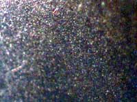
quality bearing surfaces will have slight grinding marks. In the left image below is a high quality cone magnified two hundred times. Notice the parallel marks from the grinding stone. Also note a slight pit from wear. The right hand image is a bearing magnified the same amount. It does show some surface marking, but is generally smoother than the cone or cup. Bearing surface smoothness will vary between manufacturers and between models. Some bearing system will simply "feel" smoother because they are smoother. This is why it is difficult to adjust by using a subjective feeling of smoothness. Generally, adjust bearings for the loosest setting that has no knocking or play, regardless of this relative smoothness.


The following adjustment procedures simulate the on-the-bike compression while still allowing access to the left side cone and locknut for adjustment. The bicycle frame and skewer act as a holder for the wheel and the axle. The set up of the wheel on the frame may seem unusual. Follow directions carefully.

NOTE: Some frames and dropouts will not allow clamping the wheel as described. The hub or spokes may contact the frame. It is possible to find spacers to simulate the dropout. Additionally, an alternative to the procedure below is to adjust the bearings with the wheel unclamped. Mount the wheel in the frame to test the adjustment. Remove as necessary, adjust, and re-test.

  1. Mount bike in repair stand.
  2. Remove rear wheel from bike. If adjusting front wheel, remove front wheel as well.
  3. Remove quick release skewer and springs. Remove any rubber boot covering left side cones and locknuts.
  4. Insert skewer through cog side of hub. Install quick release adjusting nut on non-cog side. There must be a gap between the skewer adjusting nut and the locknut. The quick release nut must press only on the axle, not on the locknut.

  5. Place cog side of wheel into left rear dropout. Non-cog side sits outboard of the bike, and is accessible to mechanic. If the cogs touch or interfere with the frame, remove rear cogs. Front wheel: either left or right side goes to rear dropout. Adjustment is done from side opposite clamped side.

  6. Adjust quick release until tension is same as when normally clamping wheel in bike. Resistance to closing should begin half way through swing to fully closed.

  7. Check bearings for play. Hold end of axle on non-cog side with one hand and rock rim laterally with other hand. Play in bearings will be felt as a knocking in the axle. If play is felt, proceed to step #9 below.

  8. If no play is felt, adjustment is potentially too tight. Purposely create excess bearing play as the first step to proper adjustment.
    A. Use a cone wrench and hold cone from moving. Note position and angle of wrench.

    B. Use another wrench on locknut. Turn locknut counter-clockwise to loosen.
    C. Loosen cone by turning cone wrench counter-clockwise about 1/4 turn, or 90 degrees.
    D. Hold cone from moving with cone wrench and tighten locknut. Locknut must be fully tight before play can be checked.
    E. Test for play by holding axle and moving rim laterally.
  9. If play is felt, adjustment is too loose. Tighten adjustment:
    A. Use a cone wrench and hold cone from moving. Note position and angle of wrench.
    B. Use another wrench on locknut and loosen by turning counter-clockwise.
    C. Recall angle of cone wrench and tighten adjustment by turning cone clockwise 1/32nd of a turn. Imagine cone wrench extending to the rim. Move end of wrench only the distance from one nipple to the next at the rim. This approximates 1/32nd of a turn for thirty-six and thirty-two spoke rims.


    D. Hold cone from moving with cone wrench and tighten locknut. Locknut must be fully tight before play can be checked.
  10. Test again for play by holding axle with one hand and moving rim laterally with the other hand. Rotate wheel and check for play all the way around wheel rotation.
  11. If play is still present, repeat adjustment step above until play just disappears. Remember to make small adjustments clockwise one at a time. Check for play at rim after each adjustment. It is likely it will take several small adjustments.
  12. Once play has disappeared, test final adjustment. Open skewer partially (about 45 degrees) and check again for play by rotating wheel and checking several points. If play is felt during this test, hub is adjusted.

  13. If no play is felt during final skewer check, the adjustment is too tight. To adjust, first CLOSE SKEWER, loosen locknut and loosen adjustment only slightly. Tighten locknut and check adjustment for play, then test again by opening skewer to 45-degree. Adjustment is finished when there is no play felt when skewer is closed, but some play is felt when skewer is partially open.
  14. Remove wheel from bike and return skewer and springs to normal position. Replace any rubber covers. Notice there is play in axle. This play disappears when wheel is clamped in place for use. You must use the same skewer setting for riding as for adjusting the hub.
  15. Remount cogs, if removed, and install wheel into bike. It is necessary to duplicate the quick release setting of hub adjustment when installing wheel.

    Misc. Notes: If hub will not adjust smoothly, the bearing surfaces may be worn out. If play does not disappear until bearing adjustment is very tight, right side locknut may not be tight against cone, or cups inside hub shell may be loose.

Hub Adjustment - Solid Axle Type

Non-quick release hub systems use axle nuts and washers on the outside of the dropouts to hold the wheel in place. Adjustment of solid axle hub bearings is similar to the hollow axle quick release type, but there is no need to allow for axle flex. Mount the wheel in the frame similar to quick release hubs as described above. Tighten the axle nut inside the dropout that is holding the wheel. The axle is now held tight. Check for bearing play. If no play is present, create play by loosening bearing adjustment, then adjust in small increments until play in gone. The goal is to find the loosest adjustment that has no play. Remove the wheel from the bike. The adjustment for solid axle hubs does not change when mounted in the bike.

Hub Adjustment - Cartridge Bearing Type

These types of hubs use an industrial type-bearing unit. The inner and outer rotating races and ball bearings are installed as a unit. These hubs are not serviceable in the sense they are overhauled and adjusted. When the cartridge bearings are worn, rough, or have play, the cartridge should be replaced. The bearing unit is then removed and a new one pressed in. This requires special tools and is best left to professional mechanics.
Information and photos are courtesy of Park Tool.
Visit their site at ParkTool.Com
 
Campagnolo Hub Parts, Tools, Maintenance and Tool Use Tips:
  • We stock a wide range of genuine replacement parts, bearings and tools for Campagnolo hubs. Click on the underlined text below to read more about:
  • Visit our Hub Accessories page to read about quick release skewers.
  • Visit our Campagnolo Hub Parts page to read about replacement parts for 1999 to current Campagnolo hubs.
  • Visit our Campagnolo Hub Parts page to read about replacement parts for pre-1999 Campagnolo road hubs and current Campagnolo track hubs.
  • Visit our Hub Tools page to read about tools for maintaining Campagnolo hubs.
  • Visit our Hub Overhaul and Adjustment Tips page to read about repair and maintenance procedures for most brands of hubs.


100% Satisfaction Guaranteed

At Branford Bike we want you to be happy and satisfied with everything you purchase from us. We understand that sometimes you will need to return a product because it was not quite what you wanted. You may return anything you purchase from us within 60 days and unused, for an immediate exchange or refund.

 
Click on the underlined text to go to the...

Page 11
Derailleur Tools

Hubs
Table of Contents

Branford Bike Catalog
Main Table of Contents

Page 13
Front Derailleur Adjustment Tips
Branford Bike Catalog Index
Quickly find an item or see everything that is in our catalog.
 
 
Order Online via our Secure Order Form

and receive FREE expedited processing with email confirmations.

Our Secure Order Form is easy to use. Simply fill in the boxes as you would for a traditional paper catalog order form.

Our Secure Order Form opens in a separate window that you may resize and tile behind our online catalog. After filling in your name, address and card information you may leave the order window open. Browse through our catalog and when you wish to purchase an item simply "cut and paste" the part number and description to the appropriate order form boxes.

When you are done shopping, submit your order for error checking, and then for processing. We will email you a confirmation within 10 minutes. Another, more detailed confirmation, will follow when we ship your order.

   
We accept Visa, Discover and MasterCard for payment.
We will NOT charge your card until your order is shipped.

 
Branford Bike Online Catalog - Archival Edition
brought to you by the former owner of Branford Bike, Tim Brockett via his personal web site, TimsLife.Com
This is an archival edition of the Branford Bike web site from February 2006. Complete with product photos, prices, how to articles and technical specifications it is a treasure trove of accurate, detailed and historical information.

In July of 2006 Branford Bike was incinerated by a huge forest fire. No one was hurt but the inventory and buildings were completely destroyed. I witnessed the fire and stayed until the trees were burning in my driveway. At that point I hiked from Branford Bike, through the smoke and embers, down the mountain to my Jeep 3 miles away. I took photos and wrote about the harrowing experience so everyone could see what I saw. My insurance was generous and I later rebuilt my home and started another business selling books. Read the story here.

Branford Bike was a huge part of my life for over 30 years; June 1976 to July 2006. I enjoyed those years tremendously and Branford Bike was often a labor of love. I hope you enjoy browsing through the archival catalog. If your visit brings back pleasant memories please share them with me via e-mail at timbrockett@gmail.com .

If you find any printed Branford Bike catalogs, advertisments or flyers please scan them as a PDF and email. Or you may mail them via US Post to Tim Brockett, PO Box 1711, Emigrant, MT 59027. Eventually I will post them in a Memorabilia catalog section.

Many Thanks and Best Wishes,
Tim Brockett
 
Go to our Secure Ordering Page

For more information, call: (203) 488-0482
Our phone hours are: Monday, Wednesday & Friday, 12 noon - 3 pm Mountain Time

To print this page in Netscape Navigator or Microsoft Explorer:
Choose File from the upper menu bar, click, and then click on Print...